1. Introduction to the working principle of spda100ba160
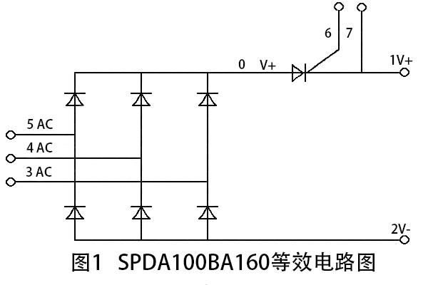
(1) The equivalent line of spda100ba160 is shown in Figure 1, and its main features are as follows:
① It can withstand 1600vdc working voltage continuously and can withstand 1700vdc working voltage in a moment;
② The current of 100adc can be output continuously, and the current of >1000adc can be output in a flash;
③ The built-in SCR module can withstand the impact capacity of current >7000a2s, and the change rate of electric flow di / dt > 150A / μ s; and because the thyristor module is also built into the cooling substrate of the rectifier bridge as the diode in the bridge, and the rectifier bridge is usually installed on the driver radiator, so its rated operating electric flow is guaranteed.
It can be seen from Fig. 1 that if the SCR module in the figure is not opened, even if the power is added to the 3, 4 and 5 feet, the current amount cannot be circulated through the thyristor module, and only through other bypass (such as slow power on resistance). The controlled silicon module can be used to control the power on slowly.
It can also be seen from Figure 1 that dfa100ba160 cocoa is divided into two parts: input part (3, 4, 5 pin) and output (1, 2) part and control part (6 and 7 feet).
(2) see Table 1 for the pin action of spda100ba160
2. The use of spda100ba160 in servo system
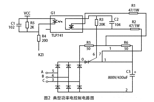
(1) a power circuit of a typical servo system with spda100ba160 as the automatic control of slow power on (see Fig. 2)
A power circuit of a typical servo system with spda100ba160 as the automatic control of slow power on
A, B and C are input terminals of 3 φ 380VAC, kzi is the control input of thyristor installed in rectifier bridge, R5 and R6 are the slow power on resistance of power line, and R6 is also the power sampling resistance value of tlp741 optocoupler.
(2) principle of line
It is shown from Figure 2 that when ports a, B and C are just sent to 3 φ 380VAC, then:
① The level sent by kzi is high, the original side of tlp741 is not connected, the side is not connected, the thyristor installed in the rectifier bridge cannot be connected. The charging current of power line is only charged to power capacitance C3 by means of three-phase full bridge, R5 and R6. Before, the upper computer should prohibit the load from power capacitor C3;
② When the upper computer detects that the change rate of working voltage on both sides of C3 capacitor is less than the specified value, the level sent by kzi is low, and tlp741 is allowed to be on. Then, the pay side is ready to trigger the thyristor conduction installed in the rectifier bridge at any time in accordance with the opening standard. At this time, if the voltage drop on the sample resistance value R6 may be small, the thyristor in tlp741 cannot be turned on, or the voltage drop in R6 is enough to make the thyristor in tlp741 on, but it is not able to make the thyristor installed in the rectifier bridge on, then the thyristor installed in the rectifier bridge may not be on during this period of time;
③ After the kzi signal sent is low and the delay is about 10ms (Objective: ensure the trigger line is ready), C3 power line is allowed to be loaded. At this time, if the voltage at both ends of C3 capacitor is higher than the working voltage (i.e. the working voltage of 0-2-pin end in Figure 2), the thyristor installed in the rectifier bridge will not be on, only in the next charging period: when the working voltage of the 0 terminal is higher than that of the 1 terminal and the voltage drop on the sampling resistance value R6 is enough to make the thyristor installed in the rectifier bridge on, the thyristor will be on. The actual wave pattern of thyristor control pole (6 and 7 terminals) measured by Fig. 2 power line with motor load (load power is about 5kW) is shown in Fig. 3 and Fig. 4.

It is shown from Fig. 3 that during the high level of triggering pulse, it is the thyristor disconnection time, which is mainly supplied power period from power capacitor C3 to load, accounting for about 1/3 of the whole pulse period; at low-level time of triggering pulse, it is the full conduction time of thyristor, charging power capacitor to power capacitor of rectifier line and supplying power period to load, accounting for about 2/3 of the whole pulse period.
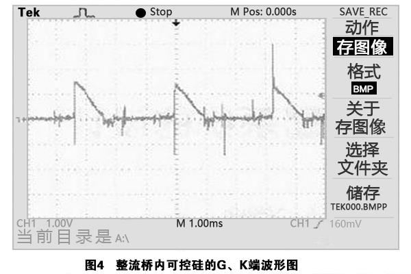
Figure 4 is a local expansion diagram of Fig. 3 wave type, or it can be calculated as the additional current to be supplied for charging the power line instantaneously: the normal value is the charging current to the capacitance C3 (corresponding to the sinusoidal part in Fig. 3), and the additional value is the current amount of work supplied to the load (the ripple part superimposed on the sinusoidal wave in corresponding figure 3). The time period in Figure 4 corresponds to the transition period of the thyristor breaking steering on, charging / load current flow through resistance values R5 and R6. Because the PWM control period of power line is 6KHz, when PWM is on, the current flow through R6, so there is trigger pulse added to the C and K poles of thyristor. When PWM is off, no electric flow flows through R6, so no trigger pulse is added to G and K poles of thyristor. Therefore, the trigger pulse frequency of thyristor is 6KHz at this time.
④ When the thyristor is disconnected in case of fault or power failure, the upper computer will disconnect the load of power line completely, and then make the kzi signal sent out is high, and then delay 1 electric period at most (=1 / (6 * 50) s ∧ 3.33ms) at most, the thyristor will be disconnected.
⑤ ) repeat 1-4, and then realize a complete control link.
3. Precautions
In the scheme line in Figure 2, note:
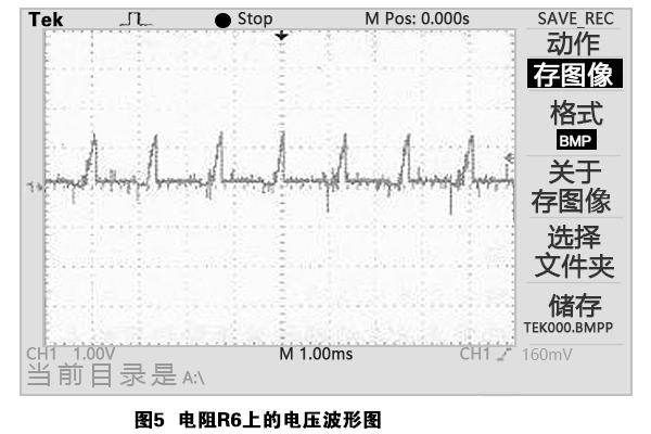
(1) resistance power: in Figure 2, from the analysis above, it can be seen that the current passing through by resistance R5 and R6 in the first delay is very large, usually during the operation with load, and the current passing through in a moment is also relatively large. Therefore In the specific application, it is important to pay attention to the power of selecting resistance R5 and R6 is large enough; and, at the moment of thyristor conduction, the instantaneous current through resistance R1 and R2 is also large, as shown in Fig. 5, that is, the waveform diagram measured by the power line with motor load (load power is about 5kW) of Fig. 2 power line:
As can be seen from the figure, R6 voltage drop is 7V, and the current amount is passed through each power supply cycle (=50hz*6=300hz). Since R2 voltage drop is embedded in 2V by thyristor g and K poles, the voltage drop on resistance R1 is ≥ 7-2=5 (V)
Instantaneous power on resistance R1: ≥ 5 * 5/47 ≈ 0.53 (W)
It can be seen that the resistance R1 needs to bear a large power, so it is also necessary to pay attention to the selection of resistance R1 and R2 power is large enough to ensure the reliability of the whole trigger control circuit;
(2) timing: when power is on, if the thyristor in the bridge fails to meet the conduction condition, the power circuit is allowed to carry the load, and the resistance R5 and R6 are easily burnt and destroyed, so When power on, it is necessary to ensure that the power line can carry load operation after fully meeting the conduction conditions required by the thyristor in the bridge; similarly, when power is off, it is necessary to fully ensure that the thyristor can be disconnected after the load is completely disconnected. Otherwise, it is very easy to cause the damage of the retarding resistance R5, R6 or even R1 and R2, but also make the thyristor possible to operate under the condition of large electric flow, which is very easy to produce high breaking overvoltage, thus damaging the thyristor in the bridge, which is also a threat to the safety work of the thyristor in the bridge;
(3) the rate of change of electric flow: in any case, it is necessary to ensure that the change rate of current quantity at any time during the thyristor conduction period cannot exceed its nominal repetition value;
(4) rated value of on-line average current: in specific use, in view of the insufficient heat dissipation of rectifier bridge, components shall be derated. The specific reduction amount shall be determined according to the specific use.
(5) driving optocoupler: in view of the strong and weak current isolation, the driving power required for thyristor conduction is very large, and the voltage withstand of the coupling side is under pressure, etc., it is necessary to carefully select the push optocoupler with built-in thyristor.
The experiment shows that only the above situation is handled well, the advantage of replacing the traditional rectifier bridge with relay as the slow power on control strategy is obvious. At present, this kind of rectifier bridge has been used in the AC and DC servo equipment of our company.
4. Analysis of the advantages of the scheme
It is shown from Figure 2 that, because the voltage drop on the slowly applied resistor R6 is used as the distribution power supply of optocoupler tlp741, the on signal that allows thyristor to be turned on is sent only when the thyristor in the rectifier bridge is on; when the thyristor in the rectifier bridge is disconnected, the opening signal that allows the thyristor to be disconnected is sent.
Therefore, the kzi level is always kept low when the power circuit is running on load. The whole process of thyristor breaking and conduction is adaptive, and no special control strategy is needed. This not only saves a group of special distribution power supply, but also does not have the synchronous pulse detected by the distribution power supply (to determine the trigger time), the isolation pulse transformer required by gate trigger, etc. which is not only necessary for the traditional thyristor trigger control circuit, but also greatly simplifies the trigger control line, making the operation of the whole trigger control circuit more reliable.
The above mentioned is the explanation of the thyristor module of three-phase rectifier bridge with thyristor module passed on by the manufacturer of the electronic transmission. The semipower is a power semiconductor power module manufacturer in the professional field of power electronics technology, providing the development, production and processing of semiconductor power module for all enterprises, and also provides the processing projects of materials for each enterprise or OEM. The main products include IGBT module, thyristor module, super fast recovery epitaxial two pole module, single-phase rectifier bridge module, three-phase rectifier bridge module, rectifier diode module, Schottky diode component power module and other power semiconductor electronic components.