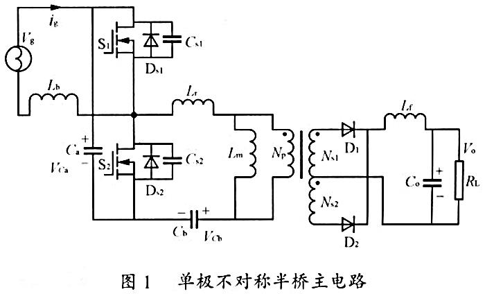
Half bridge circuit
1. Upper transistor
The common T2 shows that it has a source connected to the output (120) and a drain connected to the rail (130) to add high DC voltage;
2. Lower transistor
The common T1 shows that it has a source connected to the rail (140) to add low DC voltage, and a drain connected to the output (120);
Main components
The upper transistor control circuit (HS) is used to drive the upper transistor (T2) by adding a signal to the control end of the upper transistor (T1); and the lower transistor control circuit (110) is used to drive the lower transistor (T1) by adding a signal to the control end of the lower transistor (T1). The lower transistor control circuit (110) comprises: a third transistor (T3) with a drain connected to the output end (120), and a source connected to the anode of the diode element (D1), with the cathode of the diode element (D1) connected to the control end of the lower transistor (T1); and a fourth transistor (T4) with a drain connected to the control end of the lower transistor (T1), and a control circuit with the source connected to the anode of the diode element (D1) A standby source is connected to a rail (140) for adding a low DC voltage.

The above is the explanation of the bridge arm thyristor module by the thyristor module manufacturer semipower. semipower is a power semiconductor power module supplier with power electronics technology as its professional field. It provides the formulation, production and processing of semiconductor power modules for various enterprises and companies. In addition, it also provides the processing business of supplied materials or OEM for various companies. The main products are: IGBT module, thyristor module (SCR) module, ultra fast recovery epitaxial diode module, single-phase rectifier bridge module, three-phase rectifier bridge module, rectifier diode module, Schottky diode component power module and other power semiconductor electronic components.


